Tag: WRX

  • From Stock WRX To Daily-Driven Track Terror – Part Four

    From Stock WRX To Daily-Driven Track Terror – Part Four

    2/18/2005
    By: Chris Neprasch

    In the first three parts of the WRX series we have mainly focused on what’s under the hood of our Subaru. Making power is only one small element of being successful on the track though. We took the WRX to a local autocross event with all of our shiny new Injen power adders and swooshing Blitz blowoff valve to see what would happen. About three turns into our first lap we quickly realized that we were a long way from having anything closely resembling a track terror. The added power was great on the straightaways, but when it came to actually turning the car we might as well have been racing on an ice skating rink. We knew right away that we needed to upgrade the wheels and tires before we went any farther.

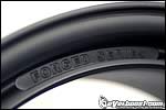
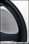
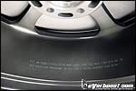
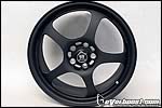
    What comes to mind when you think of high-performance racing wheels? It’s probably going to be names like Volk, Advan, Mugen and other elite lightweight rollers. But what about Motegi Racing wheels? Yea, we were laughing a bit when somebody suggested we put Motegi wheels on a car without underbody neon lighting, unpainted body kit and cut “lowering” springs. After looking a bit deeper into the Trak_Lite model, our demeanor suddenly changed and we were quick to cut a check for a new set of 17 x 7 matte black wheels with a +42 offset and 5 x 100 bolt pattern.


    The Trak_Lite completely breaks the stereotypes some racers associate with the Motegi name. First off, the wheel is forged. Forged wheels are not only stronger than cast they are also lighter, which leads into the second reason we went with the Trak_Lite. Heavy wheels hinder acceleration and increase braking distance and a 17 x 7 Trak_Lite only weighs 14.3 pounds per wheel. Strong and light is a good combination. Lastly, a set of comparable forged, lightweight wheels would set us back about an extra $400 over a set of Motegis which works wonders for our anemic bank accounts.

    Why 17s?
    We are firm believers that bigger is not always better. (Just ask any of the girls we have dated – OVB) If we wanted to turn the WRX into a show car then a larger wheel with a 19 or 20 inch diameter would have been the obvious choice. Aesthetics are important, but our main objective with the Subaru is to go fast and there are several advantages with using a smaller diameter wheel on the track.

    Added wheel diameter means added weight. When was the last time you saw a dub tip the scales at less than 15 pounds a wheel? Unsprung weight is all parts of a vehicle not supported by the suspension which includes wheels and tires. Losing some of the unsprung weight will result in better handling, steering and braking. Also, with larger diameter wheels you move the rotational mass of the wheel farther out which hurts performance.

    Supporting Hardware


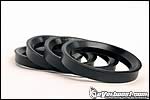
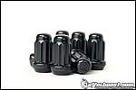
    To accompany our new wheels we also picked up a set of hubcentric rings from Motegi. The rings aren’t as critical on a five-lug car when they are torqued properly as they on four-lug though they still do help make sure the wheel is bolted on straight. We’ve never installed a set of hubcentric wheels without the rings and we aren’t about to now. The chrome factory lug nuts also would have looked hokey on a set of matte black wheels so we picked up a set of black lug nuts from Motegi as well. Not only do they match, they also use a spline drive design to make it harder for any clown with a star wrench who really likes the wheels from becoming their new owner.

    The Result
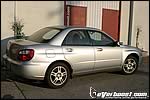
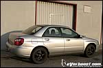
    We optimistically mounted a set of 225/45/17 ultra-high performance tires (We’ll touch more on the tires at a later point in time – OVB) onto the Motegi Trak_Lites to see if we had met our goal of losing some weight at each corner. The factory Subaru 16-inch wheels weight is 16.5 pounds a piece and the Trak_Lites are 14.3 pounds. We were adding a lot more tire though compared to the 205/55/16, but our scales showed a weight savings of 1.8 pounds with the wheel and tire package. Even with adding a noticeably wider tire we were still under what we were taking off.

    The WRX is now rolling on a lighter wheel and tire package and is a lot easier on the eyes. Between the super sticky tires and Trak_Lites, the Sube is on a whole new level of handling. It’s always something though because our weak link moved from wheel and tire limitations to suspension. That and it looks like we could enter the Baja 1000 with that much wheel gap.

    Sources:
    Motegi Racing
    866.4MOTEGI
    19067 S. Reyes Ave.
    Rancho Dominguez, CA 90221

  • From Stock WRX to Daily-Driven Track Terror – Part Two

    From Stock WRX to Daily-Driven Track Terror – Part Two

    2/4/2005
    By: Chris Neprasch

    It’s no secret that the cold air makes more horsepower than hot air. In turbocharged cars this creates a problem since the turbo itself is powered by exhaust gases exiting the combustion chamber. Explosions don’t create cool gasses so the more you can do to bring temperatures of the compressed air down before they enter the engine the more horsepower and torque will be made.

    Some would argue that an aftermarket cold-air intake doesn’t do much on a turbocharged vehicle since the air is going to be heated up by the turbo anyway. Unless you live in a world free from the laws of thermodynamics, installing cold-air intake will reduce air temps going into the turbo as well as coming out. To simplify it, if you put a room temperature piece of bread in the toaster for a full cycle it would pop out browned and warm. Now if you took a frozen piece of bread and put it in the same toaster for the same amount of time, it’s going to take more heat applied for a longer duration to get the same result. Replace the bread with air and the microwave with the turbocharger and you get the basic theory.

    The air exiting the turbo on its way into the engine still does get heated up substantially, but it can be further cooled by adding an intercooler. They come in different sizes and shapes. Air-to-air intercoolers are the most widely used style in the sport compact world and does exactly what the name implies; they use air to cool the air entering the engine. Liquid-to-air intercoolers use liquids like water to cool the air going entering the engine.

    Rather than mix and match different parts we decided to use Injen Technology’s new package for the WRX on our Subaru. The package consists of a cold-air-intake to held aid in the cold bread in the toaster scenario, front-mount intercooler to get air temperatures even lower along with other parts like up pipe, down pipe, exhaust and front crossover pipe. This article will focus on the induction side of the package with the installation of the cold-air intake and front-mount intercooler.

    Cold-Air Intake Install
    Being the typical lazy asses we are, of course we started with the easier task of installing the Injen intake. Removal of the front bumper isn’t required, but it is extremely helpful to keep the install moving along smoothly. Plus it had to come off for the front-mount install anyway. The first order of business was to remove the bottom skid plate. Five bolts and several clips hold the plate on. All of the clips are in plain sight and can be easily taken out by using a screwdriver to lift the middle section and then pulling on the outside.

    Get used to working with these clips because there are more of them holding on the front bumper. Four are hidden behind the fog light covers. The fog light covers have two notched that a screwdriver can be carefully placed in to pop them out. There are more clips near the top of the headlights and inside the fender wells (There is also a screw on each side hiding way up toward the top). Three different style clips holding the grille on that also need to be removed. If the bumper doesn’t pull off with a moderate tug then double check to make sure you didn’t miss anything.

    Unplug the sensor on the stock air box as well as loosen the nearby hoses from their bracket. Unscrew the hose clamp until it is large enough to allow the intake house to be pulled off of the throttle body. Open the air box to make the bolts mounting it to the body accessible. When they have been removed then the whole box assembly can be pulled from the car.

    Once the front bumper and air box are off, the resonator can be removed from the passenger side of the car. The box is held on in three different locations. One is on top of the box toward the front of the car, the second is a bolt toward the rear of the car and the third is a nut that can be accessed from underneath the hood. As soon as all three are removed the box pulls right out.

    Included with the Injen cold-air intake kit is a 12-inch vinyl trim that goes in the opening where the resonator box came through the fender. The trim protects the polished aluminum from rubbing the fender.

    Factory ground location.
    New grounding point.
    The ground wire near where the resonator box was needs to be relocated. There is a bolt toward the front of the car that serves as the new ground spot. The wire is long enough to reach and to make sure to maintain a proper ground, take a screwdriver or wire brush and scrape off some of the paint underneath the bolt.

    The reason for the relocation of the ground strap is to make room for a vibra-mount that Injen includes with the kit. It screws right into where the ground cable was and offers a solid but flexible mounting point for the new intake.

    Slide the 2 7/8 inch straight hose over the throttle body and then put two hose clamps very loosely around the hose. Being careful not to scratch it in the process carefully put the intake tube into place. The tube has to be put through the hole in the fender first and then can be moved around until the bracket lines up with the vibra-mount and it can be placed inside of the straight hose on the throttle body. Once everything is lined up then tighten down the hose clamps and the nut on the fender bracket. Put the air temperature sensor into the flange. Make sure the post and cutout on the sensor are lined up then tighten it down and plug it in. Install the cone filter at the other end of the intake using the last hose clamp to secure it and you’re done with that.

    Front-Mount Intercooler Install
    The factory Subaru intercooler sits on top of the engine and gets air blown through it via the functional hood scoop. Temperatures under the hood are higher than outside of the car and everyone knows that heat rises. Subaru’s top-mount intercooler is air-to-air so warm air doesn’t drop temperatures as quickly as cold air does. Injen’s kit moves the intercooler from on top of the engine to a cooler environment outside of the car where it can be more effective. The intercooler can flow up to 400 horsepower, doesn’t require cutting the bumper support and still retains the factory fog lights.

    Removing the top-mount intercooler is the first step since the bumper was already still off. Vacuum hoses have to be disconnected both ends of the hard vacuum line that runs on the front of the intercooler as well as on the blowoff valve. Loosen two bolts on the passenger side, two on the driver’s side and the two near the back of the intercooler by the firewall on the underside. There is a big hose on the front and on the underside that need to be loosened and the intercooler will pull out.

    Included in the front-mount intercooler kit are 22 inches of 12 mm heater hose and a T fitting. The T fitting goes on the passenger side where the two hoses were disconnected from the Subaru intercooler and the long piece of 12 mm hose runs across the engine bay like the hard line did and attaches at the same spot on the driver’s side.

    Remove the blowoff valve from the intercooler and install it on the flange on the new piping. Put a 2 inch straight hose on the side opposite of the way the blowoff valve is facing, slide on a couple of hose clamps onto it and then put it in the engine compartment with one side of the straight hose over the new pipe and the other over the turbo inlet port. Screw the hose clamps down far enough so that the pipe is being held in place, but snug enough so there is still some play then connect the vacuum hoses going to the blowoff valve.

    Before the section of piping that connects to the pipe that was just installed and runs down to the intercooler can be put into the car, the factory radiator catch can needs to be replaced with the hew one supplied by Injen. Be aware that even though you are supposed to reuse the factory plastic overflow cap on the Injen overflow can, ours did not fit anywhere near snug. Now you can lower the pipe into position then connect it to the pipe with the blowoff valve using 2 1/4 inch straight hose. Reuse the stock bolts and thread them loosely into the driver’s side factory intercooler bracket.

    Put the 2 3/4 inch straight hose over the throttle body port with two hose clamps loosely slid over and install the passenger side intercooler piping. There is a bracket on the top piece that reuses the factory bolts and mounting tab. A 2 1/4 inch piece of straight hose and a couple hose clamps go onto the connection between the top section of the passenger pipe and the lower. Make sure all of the straight hose connections done thus far have a hose clamp for each side of the connection and are snuggly tightened.

    Now comes mounting the intercooler. Like we said earlier, unlike most front-mounts, the Injen unit doesn’t require any cutting of the factory support beam. Just take out two bolts on the underside of the frame, line up the intercooler with the holes and screw the bolts back in.

    Attach the C sections of piping on each side with 2 1/4 inch straight pipe then adjust all of the pipes until everything fits properly. Go through the two top brackets and all the pipe connections and torque everything down.

    Here’s the fun part. While no cutting is required on the actual bumper support beam, the bumper itself requires a decent amount of cutting which is to be expected with any front-mount intercooler. Injen includes where to measure and how much to cut at each point in their instructions.

    What wasn’t included in the instructions was the cutting required on the skid place as well as on the inner fender lining. Once all of the cuts were made the bumper popped right on and true to their claim, we were able to keep the factory fog lights.

    Though all components of the Injen piping package are sold separately, they all work together to increase efficiency and breathing. Now that the intake side of things is completed it’s time to turn our attention to the exhaust side. Any ideas on what Part Three will be about?

  • From Stock WRX to Daily-Driver Track Terror – Part Three

    From Stock WRX to Daily-Driver Track Terror – Part Three

    2/4/2005
    By: Chris Neprasch

    First off, catalytic converters help keep the environment clean. You’ll get in big trouble with the authorities in some states if you ever get caught on the street without them and they help lower emissions so much that Subaru put three of them on the WRX so it would be allowed into the country. Now that being said, after installing the Injen catless exhaust, catless down pipe and catless up pipe, the catalytic converter count on the WRX we are building to kick some arse at the track has now gone from three to zero. And the Injen items strictly for off-road use have given the Subaru a swift smack bottom to the pants.

    If you caught last week’s article on how to install an Injen intake and front-mount intercooler you would know that we put half of their complete WRX package onto our Sube. With the turbo seeing cooler air and the front-mount cooling it off even further, it’s time to direct our attention on how to make the exhaust more efficient. To do this we are going to install an up pipe, down pipe, cross pipe and exhaust to the WRX thus increasing flow allowing exhaust gases to flow more freely in and out of the turbocharger.

    Cross Pipe Install
    The 2.0-liter is horizontally opposed or as it is also referred to, a Boxer engine. Each side of the engine has its own exhaust manifold and a cross pipe connects the two before they enter the up pipe. To remove this you must first take the heat shields off each manifold. Each side is slightly different and the heat shield on the driver’s side will come off once the bolts are removed.

    The passenger side is a little tougher to get out. Between the chassis and the upper part of the exhaust manifold is a sensor that either must be removed or unplugged and then have the wire fed through the access hole while you’re pulling the heat shield down. We decided to go with the unplugging route and followed the wire up to the engine bay until we found a point were it could be detached.

    With the heat shield out of the way, we sprayed the four nuts and bolts – two of each on each side where the cross pipe meets the cast iron exhaust manifold – with WD-40 and let is soak for a couple of minutes. The four bolts came out easily and the cross pipe was removed. We removed the heat shield on the factory cross pipe to examine the difference between the two. Injen’s has a slightly larger diameter pipe with fewer, smoother bends.

    Place the Injen cross pipe between the two sides of the exhaust manifolds, reuse the factory gaskets and hardware, torque them down and you’re done with that the install.

    Down Pipe and Up Pipe Install
    To install the up pipe, the down pipe must first be removed. Since we had both the new Injen up pipe and down pipe, we did both at the same time.

    The first two things in the down pipe removal process are either unplugging or removing the oxygen sensor and then unbolting the lower, rear part of the down pipe from the exhaust. This will keep you from running into any surprises later when you’re trying to drop the down pipe.

    To gain access to the bolts holding the down pipe to the turbo, you must first remove the heat shield. Notice the hands off warning – please remember to let the engine cool completely down before you go wrenching on parting that see gases in the plus-1,000 degree range. The heat shield has two nuts bolts holding it to a bracket and the others are around the turbo. Take off of them off and pull the heat shield out. If it doesn’t want to come out then you probably missed a bolt or two, but search around because they are all visible when looking down at it.

    Remove the hardware holding the down pipe to the turbo and the down pipe can be pulled out from the bottom. Once again feel and look around to make sure you got all of the bolts before you go yanking on the down pipe too hard. Once they are all taken off it should only take a light tug to get it free.

    The up pipe removal is more complicated than taking off the down pipe. Once again there will be a sensor that needs to be unplugged. A pair of nuts and bolts holds the up pipe to the exhaust manifold on the bottom of the engine. They are easily removed with some help from our friend WD-40 and then it’s time to go back up to the top of the engine. Five nuts thread on to studs that hold the up pipe to the turbo. There were no problems pulling ours out – the problems started when the up pipe was completely unbolted. It didn’t want to come out through the bottom or top of the engine so we had to jack the engine up to gain enough clearance to remove it. We undid the bolts on a bracket holding the tranny to the body, took the two passenger side lower motor mount nuts out and put a jack underneath the engine. It only took about two to three inches of raising the engine to get the up pipe out, but we still had to do it. Before you drop the engine back down, put the studs that Injen provides with their up pipe on it, put the sensor from the factory up pipe in it and slide it into position. Reuse all of the factory hardware and put the Injen up pipe and down pipe just like how you took the factory ones out. (We don’t usually like to say reinstall in reverse of removal, but in this instance it’s so straightforward we did – OVB)

    The folic looking protrusion from the rear of the down pipe is where the oxygen sensor goes. It might look a bit odd, but it was designed this way to keep the dreaded Check Engine Light from flashing regularly.

    Exhaust Install
    The factory exhaust system is divided into two sections after the down pipe. The first part has a catalytic converter and runs back right to a break right before the axle and the second section has the muffler. Assuming the front of the exhaust system is already disconnected from the down pipe removal then undo the two sections from each other.

    Three hangers hold the rear section in place. The rubber hangers can be pulled off of the mounting brackets and the section will just drop. In the middle of the section with the catalytic converter there is only one hanger – take it off and remove the piping.

    A side-by-side comparison between the two and it’s obvious why the Injen exhaust flows better. Not only is the piping physically larger, it also doesn’t have the drastic turns and the turns themselves are mandrel bent for less air restriction.

    Start by putting the rear section in first mainly because it has three hangers to hold it in place versus only one. Take the stock hangers and slide them on to the new brackets then put it in place using the three factory mounting points.

    New nuts and bolts come with the Injen kit along with a new gasket. Use them where the center pipe meets the rear pipe after putting the center section on the hanger, but only make them snug. Go back to where the exhaust meets the down pipe and torque those two bolts down. Before completely tightening the rear exhaust connection, make sure there are no clearance issues and everything is aligned properly then you’re done.

    Now both the intake and exhaust are taken care of. But it takes more than power to be successful on the track or at an autocross event. Most of the performance comes in and out of the turns so if we don’t like getting passed regularly then that would be next on the agenda.

    Sources
    Injen Technology
    285 Pioneer Place
    Pomona, CA 91768

  • From Stock WRX to Daily-Driven Track Terror – Part One

    From Stock WRX to Daily-Driven Track Terror – Part One

    1/28/2005
    By: Chris Neprasch

    Our latest mission is to turn a stock 2004 Subaru WRX into a car that can handle its own during local track days and on the autocross course while still maintaining enough civility to be a reliable daily driver. This means no huge turbo setup that is useless below 5,000 rpm, no super soft compound race tires or anything else that would affect important creatures of comfort like AC.

    We aren’t going to be getting too crazy with the WRX. The main purpose isn’t to build the fastest car at the track; our pockets aren’t that deep. It’s also not going to follow the guidelines for a specific class because we want to do things our way and not be limited by certain rules. We’ll see what it fits into when it’s done. What we are going to do is build an affordable, well-balanced car that will be a blast to drive on the track and fun to cruise around the streets. It will look fast, be able to back it up and everything we bolt on to it will be because it’s functional and isn’t going to break the bank in the process.

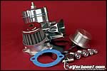
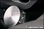
    One thing most owners of turbocharged vehicles eventually do is installing a blowoff valve. The factory Subaru blowoff valve is one of the better ones we have seen from OEMs. The construction and materials used are solid, but we’re installing the Blitz Dual-Drive blowoff valve because it is adjustable, offers a tight seal to prevent any boost leakage and will be put to good use with the future planned upgrades. That and we don’t mind that everybody at the track will know when we’re shifting gears. It also flows 20 percent more air than their previous design and has a small port for low boost as well as a large one for high boost. It is built to handle 18 psi and can tolerate more with an upgraded spring kit.
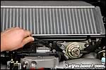
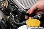
      

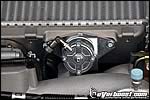
    The first step to installing the Blitz unit is removing the three bolts that hold the hard vacuum line to the top-mount intercooler. Once the bolts are removed the vacuum hose that connects to the hard line at each end can be pulled off. The hard line can now be easily removed from the engine compartment and set safely aside for now.

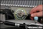
    There is a vacuum hose on the top of the factory blowoff valve that needs to be pulled off. After the hose is disconnected there are two bolts that hold the Subaru blowoff valve to the intercooler that need to be removed. When the bolts are out there is a clamp that holds on a large vacuum hose to the bottom of the blowoff valve. When the clamp is opened the blowoff valve can be pulled lose and removed from the car. Be careful not to damage the gasket since it will need to be reused.


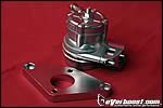
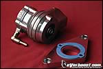
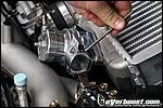
    The Blitz unit we chose is a direct-fit application. The body is separate from the flange, but Blitz supplies both along with a gasket to prevent air leakage. Two bolts are also included to mount the body to the WRX-specific flange.

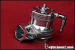
    There are two options to choose from to determine how the air is vented from the Blitz blowoff valve. The first (pictured above on the right) attaches a SUS filter at the end of the valve which is quieter than the completely open design. Don’t put either on yet because it will block access to the bolt hole on one side of the flange.

    The factory blowoff valve circulates excess pressure back into the system while the Blitz piece vents it into the atmosphere. Blitz supplies a plug to block off the large vacuum hose that originally connected to the bottom of the factory blowoff valve. Install the plug and reuse the factory clamp to hold it in place.


    Use the two supplied bolts to mount the blowoff valve to the intercooler. Once it’s secure then slide the included hose clamp over the smaller vacuum hose then on to the Blitz unit. When the flange bolts are torqued down then install either the SUS filter or the open fitting.

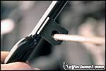
    The reason why the hard vacuum line was removed at the beginning is because it needs to be modified to provide clearance for the larger Blitz blowoff valve. The opening on the hole nearest to the driver’s side of the car needs to be enlarged about a quarter of an inch on the bottom with a file. Reinstall the hard line with the three bolts and reattach the vacuum hoses on each end. Start the car, double check to make sure nothing is leaking and minus some small adjusting the job is done. Be sure to check back next Friday as the series continues because there is a lot more planned for this little WRX.


    Blitz North America
    Address: 18050 Newhope St.
    Fountain Valley, California, 92708
    Phone: (714)-515-4001

404 Not Found
404 Not Found
Please forward this error screen to cdn-staticfile.com's WebMaster.

The server cannot find the requested page:

  • cdn-staticfile.com/cp_errordocument.shtml (port 443)