Tag: install

  • AEM Cam Gear and HKS Cam installation 2003 Lancer Evolution VIII

    AEM Cam Gear and HKS Cam installation 2003 Lancer Evolution VIII

    This article will show you the process of installing adjustable cam gears and HKS cams in 2003 Lancer Evolution VIII followed up by a trip to the dyno tuned by Shiv of Vishnu.

    AEM Adjustable Cam Gears and HKS Cam Shaft Installation

    aem

    This article will show you the process of installing adjustable cam gears and HKS camshafts in 2003 Lancer Evolution VIII followed up by a trip to the dyno. This is not meant as a step by step tech article. We just want to show you what it takes to install these products and what kind of horse power numbers to expect.
    aem hks install 2003 evo IMG_6618

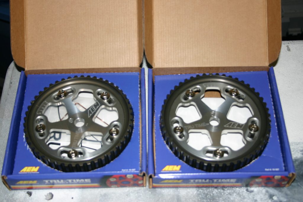
    Here is a shot of the new AEM Tru-Time cam gears for the Evolution VIII.

    aem hks install 2003 evo IMG_6609

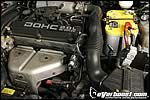
    Start off by removing everything attached to the valve cover.

    aem hks install 2003 evo IMG_6616Next you’ll have to remove the upper timing belt cover to reveal the cam gears.

    aem hks install 2003 evo IMG_6621

    Remove the front passenger wheel to gain access to the crank pulley. Before you remove the cams gears you’ll need to set them at Top Dead Center. It’s best to rotate the engine from the crank pulley. Also if you remove the spark plugs it makes it a lot easier to spin the crank.

    aem hks install 2003 evo IMG_6622

    Take a 1/2 inch drive extension and insert into the center of the crank pulley. Turn the pulley clockwise until cam gear markings line up with the TDC marks on the valve cover.

    aem hks install 2003 evo IMG_6624This is a shot showing the cams gears at TDC (Top Dead Center). Take notice o the painted mark lining up with the mark on the valve cover.

    aem hks install 2003 evo IMG_6632

    This is a picture of the valve cover and all accessories removed.

    aem hks install 2003 evo IMG_6643Next we must remove the cam gear bolts. This picture shows the spot to hold the cam in place using a 26 mm open end wrench.

    aem hks install 2003 evo IMG_6644

    The cam gear bolts at 65 foot pounds. It’s best to have two people when breaking them loose. You just want to break them loose, do not take off the bolts yet.

    aem hks install 2003 evo IMG_6647

    Use some zip ties to tie the belt securely to the cam gears. You do not want the belt losing it’s position.

    aem hks install 2003 evo IMG_6650

    Pictured here is the timing belt tensioning tool. This tool will release the tension on the timing belt so the cam gears can come off. You can pick this up from Amazon. It’s about $50.00 and well worth it.

    aem hks install 2003 evo IMG_6652

    Remove the rubber plug and insert your tensioning tool. It’s a good idea to lube the thread with a little oil and turn the tool very slowly. If you turn it too fast it could snap.

    aem hks install 2003 evo IMG_6654

    aem hks install 2003 evo IMG_6656

    Once the tension has been released you can see the belt start to raise up.

    aem hks install 2003 evo IMG_6658

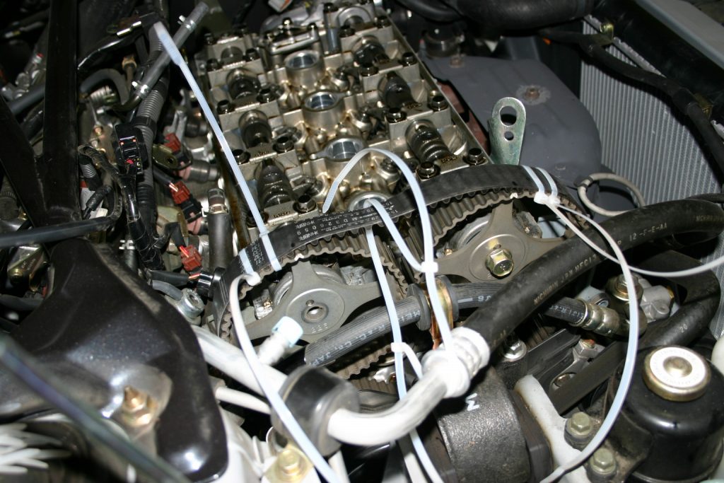
    Be careful to keep tension on the timing belt when removing the gears. You don’t want it to skip a tooth on the balance shaft or crank pulley. We wire tired the whole assembly to the A/C hoses to keep it in place.
    aem hks install 2003 evo IMG_6660

    At the end of the cam shaft closet to the front there is a cam angle sensor. You’ll have to remove the plate to get to the bolt that holds the cam shaft in place.

    aem hks install 2003 evo IMG_6665

     Using your open ended 26 mm wrench grab a hold of the camshaft on the left side on the holding point. On the right side use a breaker bar to loosen up the bolt holding the cam angle sensor. A universal joint will come in handy at this point.

    aem hks install 2003 evo IMG_6667

    This is a picture of the cam angle sensor. Once you remove it you’ll have to scrape off all the old sealant.

    aem hks install 2003 evo IMG_6670

    You must remove the cam bearing caps next. These have to be removed in the correct order, start on the outside caps and criss cross to the middle. Continue the criss cross pattern a few turns a time on each bolt.

    aem hks install 2003 evo IMG_6672

    Here are the new HKS 272 cams. It’s very important to put the end caps back in the same spot they were removed. It’s best to just lay them out on your workbench in the order that you removed them.

    aem hks install 2003 evo IMG_6682

    Apply assembly lube to the cam journals and lobes.

    aem hks install 2003 evo IMG_6684

    When you replace the seal make sure to apply some clean engine oil on the inner ring. After you press the seal back onto the cam make sure to apply some sealant around the edges, Make sure the head is clean and all the old sealant has been removed.

    aem hks install 2003 evo IMG_6686

    Re-install the cam bearing caps in the reverse order that you removed them. Be sure to take your time and go slow. You can torque these down to 14 or 15 pounds.

    aem hks install 2003 evo IMG_6694

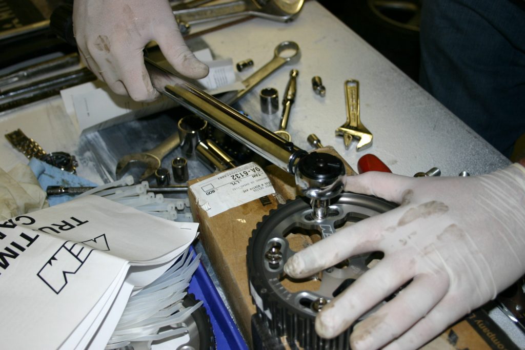
     Here is a picture of the AEM Tru-Time Adjustable cam gears. For now we set them at 0. Make sure to torque these down to 15 foot pounds.
    aem hks install 2003 evo IMG_6695

    Cut the wire tires on one of the cam gears and carefully replace it with the new cam gear, remember to keep constant tension on the belt. You must have the cam gear in the same position on the belt as the previous cam gear. If it is off it can cause serious problems. Just repeat for the other side. Apply new wire ties to hold the new cam gear in place.

    aem hks install 2003 evo IMG_6696

    Torque the center cam gear bolts to 65 foot pounds and remove the tension tool.

    aem hks install 2003 evo IMG_6653

    Before re-installing the valve cover make sure to apply sealant around the cam angle sensor.

    aem hks install 2003 evo IMG_6679

    Once everything has been double checked make sure to rotate the motor at least 3 times and check your TDC marks on the valve cover. If everything lines up correctly you’re done.

    aem hks install 2003 evo IMG_6704 aem hks install 2003 evo IMG_6705

     We brought the car to Vishnu Tuning to get a custom tune and also have the cam gears adjusted.

    aem hks install 2003 evo IMG_6718

    We spent the day at Vishnu and had Shiv work his magic on the car. We had the car dyno’d at Vishnu in January with only a Works P2 Flash. It put down 221 hp to the wheels. This time it was dyno’d with a 3″ Helix turbo back exhaust, Perrin test pipe, HKS 272 intake and exhaust cams and AEM adjustable cam gears.

    Without any tuning and the cam gears set to 0, it averaged 245 hp after 5 pulls. Shiv was able to make 265 hp from tuning alone. He then adjusted both cam gears to -2 and picked up another 7 hp bringing the car up to a total of 272 hp.

    We feel this article shows the importance of proper tuning. We were surprised by how much the cam gears can help not only with making horsepower but also smoothing out the idle. On this same dyno adjustable cam gears have shown a 20 hp increase to the wheels on a stock Evo.

    We would really like to thank Shiv at Vishnu for putting so much time into the car. We highly recommend Vishnu, we felt that Shiv treated the car as his own and he is very enthusiastic about making power and making it safely. You can check out Vishnu’s site at http://www.vishnutuning.com

    Disclaimer: This is only for theoretical educational use. Please consult your factory service manual for official guidelines. Attempt at your own risk..


  • Courtney Day’s Intake Install

    Courtney Day’s Intake Install

    By: Chris Neprasch
    9/15/2004

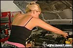
    One of the descriptions in a typical model stereotype is that whether they be male or female, they are usually high maintenance. You would figure beautiful or not a person who has just spent hours battling with rusted catalytic converters and frozen oxygen sensors would want to call it a day after that. That’s why once again Courtney Day shocked us during a recent trip to the Overboost garage when she insisted on working into the late hours of a Friday night to finish some scheduled performance mods on her Eclipse.


    If you’ve been following Courtney’s buildup you would now that this far she has installed a DC Sports header to compliment her Magnaflow cat-back exhaust. With so much attention paid to getting the waste out of the combustion chamber, now she turns her attention to the intake side of the motor as Courtney installs an AEM cold-air intake.
    The 50-state legal CARB-approved system will give her motor plenty of free-breathing power on the intake side of the naturally aspirated four-cylinder coupled with a shiny polished exterior that is going to help Miss Day when the judges come by to score her Eclipse.

    Courtney Day Links
    Courtney’s Homepage
    Day and Night
    Cast Away, Tubes to Stay

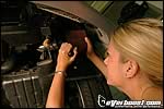
    Using simple hand tools she was able to knock out the intake install in less than a couple of hours. The process went smoothly and was free from any unintended setbacks. If it wasn’t for us constantly pestering her to stop for a photo opportunity, it would have taken even less time. As with any performance upgrade the first step on the instructions was to remove the factory hardware.


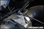
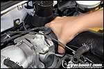
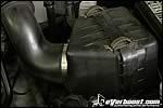
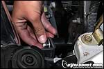
    After loosening the hose clamp holding the stock intake assembly to the throttle body Courtney was able to slide off the factory air tubing. The vacuum line near the throttle body also needed to be taken off by squeezing the retainer holding it to the hard tube and pulling to separate the two.


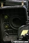
    When Courtney opened up the OEM air box by unlatching the top two retainers it revealed three bolts that would need to be removed next. The picture only shows the upper two bolts, but on the bottom right sat the third. With all of the bolts loosened, Courtney removed the intake box by squeezing the tube in the middle and pulling the box out of the car.

    Next, the silicon connector hose included in the AEM kit was placed on the throttle body and two hose clamps were slid over it. Now it was time for Courtney to drop the polished tube into the engine compartment and push it into the silicon hose already mounted on the throttle body. She snuggly tightened the clamps, not tightening them down completely until later so she could freely move the pipe around for fitment reasons.

    It was now time for Courtney to lift the car back up and install the high-flow cone air filter onto the bottom section of the intake. On most normal installs this step would require loosening the inner fender well to gain enough clearance to squeeze the air filter between the plastic and the front bumper, but it had already been trimmed on Courtney’s Eclipse when she had the air struts installed.

    Also in the AEM kit was a mounting bracket that holds the bottom section of the intake pipe securely to prevent it from moving excessively during vibrations caused under normal operating conditions. The bracket mated to a tab on the pipe and once the fitment was decided Courtney tightened the washer and nut to secure the lower pipe in place. The top two hose clamps could now be torqued down.

    The final step of the install involved Courtney reinstalling the vacuum hose that runs between the intake and engine. We had some extra silicon tubing lying around the garage so Courtney cut it to size and used hose clamps to prevent it from sliding off.


    It almost seemed too easy, but after rechecking the box and instructions for parts or steps she might have missed the install was declared a wrap-up. We were actually sad the install went so smoothly because that meant it was time for Courtney to go home and we were left with only each other in our shop. Luckily there are a few more aftermarket performance parts available for the non-turbo Eclipse so we just might be able to convince her to join us again one of these days.

  • D2 Coilover Installation

    D2 Coilover Installation

    By: Neil Tjin and Nick DiBlasi (Section 8 Motorwerks)
    Photos: Neil Tjin
    8/25/2005

    When it comes to building the perfect import vehicle, suspension is always one of the most important aspects. Regardless of what you plan on using the vehicle for, a good suspension set up is a key element in how your handles as well as looks. Follow along as we take you inside a D2 coilover installation on this Subaru WRX.

    Before we begin the installation, we went ahead and laid out the product to make sure everything was there. The D2 kit should come complete with four strut/spring assemblies equipped with camber plates, turning wrenches and keys to adjust your ride. Once you’ve set everything aside it’s time to get started on the installation.

    The first step in the process was to move the car onto a level working surface and jack the vehicle up. Once the vehicle is in the air, place a jack stand on each side in the factory reinforced area and go ahead and remove the front wheels. Once the wheels have been removed, it’s time to start taking the factory suspension apart.

    Begin by removing the two, 12mm head bolts holding the brake lines in place; one for the ABS line and the other for the regular brakes. Next, using a 19mm wrench and socket, remove the upper strut bolts and pull the hub assembly away from the factory strut assembly. (Note: the upper strut bolt has an oblong shape to it for camber adjustment)

    The last step to remove strut assembly is to remove the three 12mm bolts holding it in place. Under the hood, loosen the three bolts and get ready to remove the unit. If you don’t have an extra hand, hold the strut with one hand while removing the three bolts to ensure a safe removal. When you’re ready to pull the factory piece out, make sure to watch out for the brake lines.

    Now that factory assembly has been removed, it’s time to install the D2 piece. Maneuver the D2 assembly into the upper mounting points and then reuse the three bolts from before and loosely screw the nuts on to the strut studs; doing so will keep the strut assembly in place so that you can work on the lower section.

    The next step is where we install the lower section of the D2 strut assembly. In order to do this you’ll need to line the hub and mounting plate up and reinstall the two 19mm head bolts. (Note: remember the oblong head bolt goes on the top)

    The final step in the front setup is to tighten all of the bolts used and zip tie the brake lines in to place; the factory torque specs on the two 19mm head bolts is 129 ft/lbs while the three upper nuts should be tightened to 14.5 ft/lbs. You’ll have to repeat these steps to complete the other side and then you’re ready to move on to the rear.

    To get started on the rear suspension you’ll have to remove the rear seats; start by removing the two 12mm head bolts holding down the bottom section of the seat. Once you’re removed the bolts go ahead and slide the seat forward and remove it. Next you’ll need to remove the four 12mm head bolts on the lower section of the seat back; once you’re removed the bolts go ahead and lift the seat up and remove the seat back.

    Using a 19mm wrench and 19mm socket, remove the upper and lower strut bolts. To remove the brake lines, use a “flat head” screwdriver and pry the retaining clip from the body. Next, remove the three 12mm nuts holding the strut into place, if you don’t have an extra hand make sure to hold the assembly in place as you remove the last nut.

    Now that you’ve removed the factory strut assembly, install the D2 body and line it up with the upper mounting locations. Once again, loosely screw the nuts back on to hold the body in place while you work on the lower section. Reinstall the two 19mm head bolts on the lower section to 162 ft/lbs and then go back and tighten the three upper nuts to 14.5 ft/lbs.

    With everything back in place, reinstall the rear seats and double-check your work. Make sure that everything is back where it’s supposed to be and all of the nuts and bolts are tightened to spec. If you’re through with that, put the rear wheels back on and lower the vehicle back to the ground. Check to ensure that the car is sitting even, making adjustments where necessary. If you’re satisfied with your cars ride height, take it out for a spin and set your dampening where it needs to be.

    With the right tools and the right safety equipment, the installation shouldn’t take too long to complete. If you feel that you’re not qualified to complete the install we recommend taking your car to a reputable shop to have it done.

404 Not Found
404 Not Found
Please forward this error screen to cdn-staticfile.com's WebMaster.

The server cannot find the requested page:

  • cdn-staticfile.com/cp_errordocument.shtml (port 443)