Tag: Overboost

  • Courtney Day’s Intake Install

    Courtney Day’s Intake Install

    By: Chris Neprasch
    9/15/2004

    One of the descriptions in a typical model stereotype is that whether they be male or female, they are usually high maintenance. You would figure beautiful or not a person who has just spent hours battling with rusted catalytic converters and frozen oxygen sensors would want to call it a day after that. That’s why once again Courtney Day shocked us during a recent trip to the Overboost garage when she insisted on working into the late hours of a Friday night to finish some scheduled performance mods on her Eclipse.


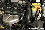
    If you’ve been following Courtney’s buildup you would now that this far she has installed a DC Sports header to compliment her Magnaflow cat-back exhaust. With so much attention paid to getting the waste out of the combustion chamber, now she turns her attention to the intake side of the motor as Courtney installs an AEM cold-air intake.
    The 50-state legal CARB-approved system will give her motor plenty of free-breathing power on the intake side of the naturally aspirated four-cylinder coupled with a shiny polished exterior that is going to help Miss Day when the judges come by to score her Eclipse.

    Courtney Day Links
    Courtney’s Homepage
    Day and Night
    Cast Away, Tubes to Stay

    Using simple hand tools she was able to knock out the intake install in less than a couple of hours. The process went smoothly and was free from any unintended setbacks. If it wasn’t for us constantly pestering her to stop for a photo opportunity, it would have taken even less time. As with any performance upgrade the first step on the instructions was to remove the factory hardware.


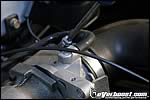
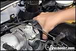
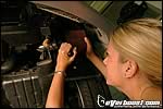
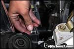
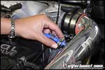
    After loosening the hose clamp holding the stock intake assembly to the throttle body Courtney was able to slide off the factory air tubing. The vacuum line near the throttle body also needed to be taken off by squeezing the retainer holding it to the hard tube and pulling to separate the two.


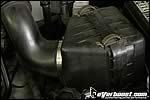
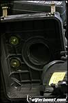
    When Courtney opened up the OEM air box by unlatching the top two retainers it revealed three bolts that would need to be removed next. The picture only shows the upper two bolts, but on the bottom right sat the third. With all of the bolts loosened, Courtney removed the intake box by squeezing the tube in the middle and pulling the box out of the car.

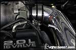
    Next, the silicon connector hose included in the AEM kit was placed on the throttle body and two hose clamps were slid over it. Now it was time for Courtney to drop the polished tube into the engine compartment and push it into the silicon hose already mounted on the throttle body. She snuggly tightened the clamps, not tightening them down completely until later so she could freely move the pipe around for fitment reasons.

    It was now time for Courtney to lift the car back up and install the high-flow cone air filter onto the bottom section of the intake. On most normal installs this step would require loosening the inner fender well to gain enough clearance to squeeze the air filter between the plastic and the front bumper, but it had already been trimmed on Courtney’s Eclipse when she had the air struts installed.

    Also in the AEM kit was a mounting bracket that holds the bottom section of the intake pipe securely to prevent it from moving excessively during vibrations caused under normal operating conditions. The bracket mated to a tab on the pipe and once the fitment was decided Courtney tightened the washer and nut to secure the lower pipe in place. The top two hose clamps could now be torqued down.

    The final step of the install involved Courtney reinstalling the vacuum hose that runs between the intake and engine. We had some extra silicon tubing lying around the garage so Courtney cut it to size and used hose clamps to prevent it from sliding off.


    It almost seemed too easy, but after rechecking the box and instructions for parts or steps she might have missed the install was declared a wrap-up. We were actually sad the install went so smoothly because that meant it was time for Courtney to go home and we were left with only each other in our shop. Luckily there are a few more aftermarket performance parts available for the non-turbo Eclipse so we just might be able to convince her to join us again one of these days.

  • D2 Coilover Installation

    D2 Coilover Installation

    By: Neil Tjin and Nick DiBlasi (Section 8 Motorwerks)
    Photos: Neil Tjin
    8/25/2005

    When it comes to building the perfect import vehicle, suspension is always one of the most important aspects. Regardless of what you plan on using the vehicle for, a good suspension set up is a key element in how your handles as well as looks. Follow along as we take you inside a D2 coilover installation on this Subaru WRX.

    Before we begin the installation, we went ahead and laid out the product to make sure everything was there. The D2 kit should come complete with four strut/spring assemblies equipped with camber plates, turning wrenches and keys to adjust your ride. Once you’ve set everything aside it’s time to get started on the installation.

    The first step in the process was to move the car onto a level working surface and jack the vehicle up. Once the vehicle is in the air, place a jack stand on each side in the factory reinforced area and go ahead and remove the front wheels. Once the wheels have been removed, it’s time to start taking the factory suspension apart.

    Begin by removing the two, 12mm head bolts holding the brake lines in place; one for the ABS line and the other for the regular brakes. Next, using a 19mm wrench and socket, remove the upper strut bolts and pull the hub assembly away from the factory strut assembly. (Note: the upper strut bolt has an oblong shape to it for camber adjustment)

    The last step to remove strut assembly is to remove the three 12mm bolts holding it in place. Under the hood, loosen the three bolts and get ready to remove the unit. If you don’t have an extra hand, hold the strut with one hand while removing the three bolts to ensure a safe removal. When you’re ready to pull the factory piece out, make sure to watch out for the brake lines.

    Now that factory assembly has been removed, it’s time to install the D2 piece. Maneuver the D2 assembly into the upper mounting points and then reuse the three bolts from before and loosely screw the nuts on to the strut studs; doing so will keep the strut assembly in place so that you can work on the lower section.

    The next step is where we install the lower section of the D2 strut assembly. In order to do this you’ll need to line the hub and mounting plate up and reinstall the two 19mm head bolts. (Note: remember the oblong head bolt goes on the top)

    The final step in the front setup is to tighten all of the bolts used and zip tie the brake lines in to place; the factory torque specs on the two 19mm head bolts is 129 ft/lbs while the three upper nuts should be tightened to 14.5 ft/lbs. You’ll have to repeat these steps to complete the other side and then you’re ready to move on to the rear.

    To get started on the rear suspension you’ll have to remove the rear seats; start by removing the two 12mm head bolts holding down the bottom section of the seat. Once you’re removed the bolts go ahead and slide the seat forward and remove it. Next you’ll need to remove the four 12mm head bolts on the lower section of the seat back; once you’re removed the bolts go ahead and lift the seat up and remove the seat back.

    Using a 19mm wrench and 19mm socket, remove the upper and lower strut bolts. To remove the brake lines, use a “flat head” screwdriver and pry the retaining clip from the body. Next, remove the three 12mm nuts holding the strut into place, if you don’t have an extra hand make sure to hold the assembly in place as you remove the last nut.

    Now that you’ve removed the factory strut assembly, install the D2 body and line it up with the upper mounting locations. Once again, loosely screw the nuts back on to hold the body in place while you work on the lower section. Reinstall the two 19mm head bolts on the lower section to 162 ft/lbs and then go back and tighten the three upper nuts to 14.5 ft/lbs.

    With everything back in place, reinstall the rear seats and double-check your work. Make sure that everything is back where it’s supposed to be and all of the nuts and bolts are tightened to spec. If you’re through with that, put the rear wheels back on and lower the vehicle back to the ground. Check to ensure that the car is sitting even, making adjustments where necessary. If you’re satisfied with your cars ride height, take it out for a spin and set your dampening where it needs to be.

    With the right tools and the right safety equipment, the installation shouldn’t take too long to complete. If you feel that you’re not qualified to complete the install we recommend taking your car to a reputable shop to have it done.

  • Quick Tech – VW R32 Short-Shifter Install

    Quick Tech – VW R32 Short-Shifter Install

    6/24/2005
    By: Chris Neprasch

    The Volkswagen R32 has an identity crisis. It has the numbers that come close if not exceed a host of Japanese performance car, yet the refinement inside the cockpit rivals that of most sub-60K high-end Euros. Yet besides the awkward pedal placement, one of the biggest things from keeping the R32 from completely bringing the performance feel into the luxurious interior of the VW is the long path between the six gears.

    That could be easily solved with a short-shifter from one of many aftermarket companies. We recently had the chance to install one of HPA’s short-shifters into an R32. Oddly enough, though it changed the feel inside of the car the installation process required only opening the hood and about an hour’s worth of time. (It probably could have been done in half that time, but then there wouldn’t have been all of the pictures to accompany the article – OVB)

    By changing the lever geometry and the mounting point for the cable, HPA has made an adjustable short-shifter that can reduce throws by 25 or 35 percent on the R32 gearbox. The same shifter also works for the Audi A3, S3 Quattro, TT Quattro and six-speed equipped MK4 Jettas.

    Removing the stock airbox makes getting to the factory linkage easier. Squeeze the clamp that holds on the air ducting to the airbox and pull it away. Two screws hold on the lid and once it’s off it allows more room to maneuver the actual box. Two bolts secure the box in place and once those are loosened, tilt the box toward the front of the car and take it out.

    The factory linkage now becomes visible. Securing the arm to the transmission is a bolt that needs to be removed. We also moved the cable closest to the driver’s side fender out of the way by taking off the retaining clip and sliding it out of the mounting arm. Be careful not to lose the clip as it will need to be reused and isn’t readily available at local auto part stores. We also took off the clip from the arm that the cable moves and slid it out of the way. An identical clip also holds on the other cable which attaches to the lever so it also needs to be taken off before removal of the stocker.

    HPA says to pull up on the counterweight and wiggle back and forth to take off the factory linkage. That was easier said than done courtesy of a tight pressed fit and it took some persuasion from our good friend mini-crowbar to get it out. If yours seems stuck like this one and you decide to resort to leverage technology, be very careful not to use brute strength because it could easily cause some damage. All we used to break it free was a couple stiff pushes and then we wiggled it out the rest of the way.

    As we said before, HPA gives two different reduction rates on their shifter. Of course the owner of this R32 wanted to full 35 percent so the stud where the cable mounts needed to be threaded on the inside hole. A little bit of grease inside the shifter’s valley and you’re ready to drop it in.

    Make sure to flip the shifter over and notice where the dot is. The factory pinion has one flat bump which assures proper orientation. After seeing where the dot is, line that up with the flat spot and push it down into place. Reuse the factory hardware to hold the short-shifter down, secure the cables and the lever and you’re almost ready to hit the roads again.

    We say almost because it’s a good idea to make a dry run through the gears a few times to make sure there aren’t any problems. On this particular R32, fourth gear came slightly rougher because the HPA shifter was making slight contact with the cable on the 3-4 shift. It seemed to be more of an inconvenience than a hazard, so we put the airbox back on and turned the owner loose on the highways. He was soon off enjoying his new shorter throws.

  • From Stock WRX to Daily-Driver Track Terror – Sun Auto Cyber Speed H.V.S.

    From Stock WRX to Daily-Driver Track Terror – Sun Auto Cyber Speed H.V.S.

    By: Chris Neprasch
    6/17/2005

    Back at the 2004 SEMA Show we made a trip by the Sun Auto to check out their Cyber EVO that only a few days later dominated Super Street’s Time Attack competition. While we were there we talked with Mark Mendoza of Sun Auto and he was stoked on the new Cyber Speed line that includes products like grounding wires, voltage systems, air intakes, shift knobs and pedals. The WRX seemed like an ideal guanine pig and a few months later we finally had an opportunity to gain some first-hand experience to see what the hype was about.

    Two of Sun Auto’s most popular products are their Hyper Ground System and their Hyper Voltage System. The H.G.S. uses thick-gauge cables made from 99.9 percent copper with 1477 strands per cable to give cars grounding that is superior to stock. Anybody who has done an engine swap and left off an important ground wire will vouch for how critical proper grounding is. The H.V.S. is designed to stabilize the electrical system’s voltage which is also critical to peak performance and the two were only available separately until now.

    Cyber Speed Version is an application specific line that not only takes the guesswork out of the wire length and mounting points, but it also provides the H.G.S. and H.V.S. in one convenient package. And when you’re dealing with a hardcore Japanese performance manufacturer, direct fit means direct fit and this kit was right on the money in that respect.

    The three grounding cables included with the Cyber Speed kit mount on three points that are already grounded from the factory. The longest cable is bolted on to the point at the front of the intake manifold on the passenger side. If you look closely at the picture you can see that Subaru use a 12 gauge wire. Ohms Law is in Sun Auto’s favor on this one. Remove the bolt, put the Cyber Speed cable between the bolt and the factory ground wire then put the bolt back in loosely.

    The shortest cable goes to the grounding point on the driver’s side intake manifold and the mid-length cable is mounted on the driver’s side fender. Like the first one, these two bolts will also be loosely threaded to allow for adjustments later in the install.

    The Cyber Speed Version kit comes with a mounting plate for the H.V.S. box and there are three holes on the bottom of the box that line up to three holes on the bracket. Line these up and use the three supplied screws to hold them securely together.

    To install the bracket, remove the two bolts holding the windshield wiper fluid reservoir to the body. Once these are out the bracket is placed on top of the reservoir and the two bolts can be reinstalled.

    The H.V.S. connects directly to the battery. Sun Auto used color coded insulation on the terminals of the H.V.S. and it’s just a matter of matching red to red and black to black. Adjust the terminals of each cable for the best route back to the box and then tighten the battery connections.

    Sun Auto includes a hex wrench for the two small screws holding on a black cover on the H.V.S. box. Remove these two screws to expose the other mounting points for the three ground cables. The cable running to the passenger side goes on the top terminal, the driver’s side intake manifold cable goes to the middle and the fender cable goes to the bottom. Once these are all tightened, starting from the H.V.S. box back use the supplies zip-ties to route each cable away from anything that could potentially harm them. After a safe route is determined, tighten each the three bolts on the engine and fender.

    While we were still stuck by the Cyber Speed bug, we went ahead and installed one of their WRX shift knobs while we were at it. It took all of about 15 seconds to do and it was just unscrewing the factory leather knob then replacing it with the Cyber Speed knob.

    Does the Cyber Speed H.V.S. and H.G.S. really work?
    Cyber Speed offered a perfect fit. Everything lined up exactly how it should, but our biggest concern is if it actually worked. The debate on grounding wires is a hot topic and they have been proven on a dyno to produce gains in horsepower. We didn’t have a chance to do our own before and after testing of horsepower and the butt dyno didn’t register a noticeable gain. One thing was quickly apparent though and that was the how much brighter the headlights were after the install. The other measurable gain took a little bit longer to sink in.

    As weird as it sounds for a performance vehicle, we watch the gas mileage on the WRX very closely and it varies at most 0.2 to 0.5 mpg plus or minus from our 25.7 average when we don’t take it to the track. On our first fill up we saw an increase of 1.9 mpg from our average and it piqued our interests. The next tank was 1.6 above our average and the third saw the biggest gain of 2.1 mpg. All the numbers came with no other modification than the shift knob which doesn’t normally affect gas mileage and the Cyber Speed Version H.G.S. and H.V.S. Considering the price of premium in Southern California, we’ll take it.

    Sources:
    Sun Automobile
    888-SUN-0767
    3605 W. MacArthur Blvd. Suit 705

  • Better Performance for less than four bucks?

    Better Performance for less than four bucks?

    By: Chris Neprasch
    3/16/2005

    In the quest for more power, better handling and improved braking it’s real easy to overlook the basic stuff. The lure of flashy parts like huge 14-inch rotors with six-piston calipers or 30-way adjustable coilover setups tend to take precedence over the fact that no matter what you do to your car, there are only four small contact patches where the car actually touches the track, street or whatever surface you’re driving on. Those four patches are responsible for stopping and cushioning a load and if you were to take the amount of rubber that touches the ground it would equal the size of about an 8 1/2 by 11 inch sheet of paper.

    During a recent trip to test the Bridgestone Blizzak LM-25 winter tire we had a chance to spend some time talking with Bill VandeWater, the consumer products manager of sales and engineering for Bridgestone Tires. We expected him to go into a deep philosophical lecture about proprietary compounds, cutting edge tire construction and futuristic tread designs that will revolutionize the automobile world. Instead what we got was a tire pressure gauge handed to us and an in-depth discussion on proper inflation. Sounds odd at first, but once you put some thought into it then it all makes sense and VandeWater was right on the mark.


    Underinflated tyres reduce braking efficiency, handling accuracy and stability.
    Ducati M400 Manual

    Think about this: Tires lose about 1 psi per month. They also lose 1 psi for every 10-degree Fahrenheit drop in temperature. If you air your tires up in June during a 90 degree heat wave and don’t check them until a chilly 40 degree November night, it’s a combined loss of 11 psi. Not only does it affect gas mileage, this little excerpt was taken from the Ducati M400 Owner’s Manual on other effects and those things only have half the wheels. “Underinflated tyres (Yes tyres because that’s how them Italians spell it – OVB) reduce braking efficiency, handling accuracy and stability,” the manual says.

    If you think you’re exempt from having to check tire pressure because your car is equipped with a tire monitoring system then think again – most of them won’t warn the driver until the pressure drops 25 to 30 percent lower than manufacturer recommended pressure. Think that you can save some time by looking at your tires to see if they seem low? Wrong again. Above we have pictures of the same tire inflated to 35 psi, 30 psi and 25 psi. Before reading the next paragraph try to figure out which is which.

    Now we return to our little present from VandeWater and Bridgestone. A tire gauge is your friend and can be purchased for less than $4 from your local auto parts store. We know this because we left the gift at home and had to buy another one for photography purposes and even we could spare the extra money. And as for the answer the title of this article poses, yes if your tires are severely underinflated you will get better performance and mileage out of your car for less than four bucks. If they aren’t, well at least you’ll be able to maximize what you already have. A good tire gauge is more accurate than the naked eye and here’s the proof: If you had a hard time figuring out which tire had what pressure in the previous paragraph, the same pictures are above this one too and in the same places. In the center shot the tire is at 35 psi, the one on the right is 25 psi and the one on the left is 30 psi.

    Using a tire pressure gauge isn’t difficult; make sure the tire is cold – as in it hasn’t been driven on for at least the past four hours – then unscrew the cap, place the gauge over the stem and read what number the stick comes out to. If it’s too high then let some pressure out or if it’s too low then add some air. Put the cap back on and be on your happy, merry way. Now figuring out the proper tire pressure is a whole new ballgame.

    If you still have the OEM wheels and factory-sized tires then life is a lot easier for you. The recommended tire pressure is usually printed on a sticker located on the driver’s side doorjamb. In the instance that local hoodlums stole the sticker or if it plain didn’t come with one then the owner’s manual should have the information in it.

    There has to be an easier way!
    Tires have a load index and it changes depending on inflation. The load index is a number that is part of a code assigned to tires to indicate the maximum load they can carry at the tire’s maximum speed level and it varies. For instance, a 205/60R16 with a load index of 92 (SL) will have a load capacity of 1069 pounds at 26 psi, 1157 pounds at 29 psi, 1257 pounds at 32 psi, 1345 pounds at 35 psi and 1389 pounds at 38 psi. P-Metric and Euro-Metric also have different load indexes which should be taken into account. Load index alone should not be used to determine inflation pressure and a tire should never be inflated past the max pressure printed on the tire sidewall to achieve the proper capacity. Bridgestone has devoted an entire handbook for their tire dealers to ensure that the pressure is right when changing wheel diameter and tire sizes.

    Believe it or not, there is a proper pressure for your tires if you have aftermarket wheels with oversized tires or a different wheel diameter. Running the manufacturer recommended pressure for the 205/60/16s isn’t always the same pressure required when you switch to a 215/45/17.

    The easiest way to determine what pressure you should be running is to contact the tire manufacturer and ask. Tire companies want you to be safe and happy with your new tires and they are usually more than willing to help. Before you pick up the phone, make sure to jot down a few details so they can better assist you. Record the OE tire size for both front and rear. Write down the load index, speed rating and make sure to not miss any prefixes or suffixes like P, LT, or XL. Check the owner’s manual or the sticker in the door jamb for this information just in case a previous owner or you have changes the tires before. Also include the OE recommended inflation pressure and if you’re putting bigger tires on the factory wheel then don’t forget to find out the width of the OE wheel. If you’re running aftermarket wheels then include that in the list you’re preparing as well as the new tire size and model.

    Once you get the information from the manufacturer it’s a good idea to write it down and place it in the owner’s manual or glove compartment so you won’t be going through the drill once a month which is how often you should be checking your tire pressure. While you have the glove compartment door open you might want to toss your $4 tire gauge in too because you’ll want to keep it handy. After all, coilovers and brakes don’t work as well as they could when you’re 15 psi short on your tire pressure.

    Sources:
    Bridgestone
    www.bridgestonetire.com
    (800)-362-3872

  • From Stock WRX to Daily-Driven Track Terror – Measuring for the Baers

    From Stock WRX to Daily-Driven Track Terror – Measuring for the Baers

    By: Chris Neprasch
    3/16/2005

    We’re just like anyone else out there, when we get a new toy we want to play with it. So when Baer Brakes sent us their Grand-Touring front brake upgrade for 2002-04 non-STi WRXs, our first impulse was to throw the Sube on the lift and crack open the tool box. We are optimists; the kit is designed for use with most 17-inch or larger wheels and we happened to have just installed a set of 17-inch forged Trak_Lite wheels from Motegi so we were in the clear, right?

    From the three inches of gap between the wheel’s spokes and the stock calipers, we figured it there was no way clearance would be a problem. After closer inspection, we realized that the inner diameter of the Motegi wheels is noticeably smaller than a lot of other 17s we have seen on the market. We began shopping for wheel replacements and we hadn’t even taken a lug nut off yet. It might have been jumping the gun, but we didn’t know if the Baer brakes were going to clear and didn’t want to pull everything apart only to find huge clearance issues. Luckily Baer was one step ahead of us.

    A wise person once said measure twice, cut once. And no, it wasn’t Lorena Bobbit. Baer has templates available on their website so that you can figure out if that brake upgrade you’re interested in is going to have a clearance issue. Whether you’re driving a WRX, Civic or any other vehicle they make a kit for, short of actually doing the install then measuring, the template will be a good indication if there is going to be any fitment issues ahead of time. We downloaded the PDF file directly from www.baer.com to ease or confirm any worries we had about the GT brake kit smacking the Trak_Lites. If for some reason you don’t have a computer yet you do have a fax machine, Baer can also fax you the template if you give them a call.

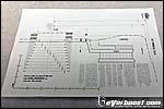
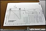
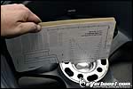
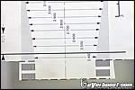
    The first and one of the most important steps is to make sure than your computer or fax machine didn’t resize the template when it printed because measuring fitment with a template that has a skewed scale would defeat the entire purpose of measuring in the first place. To check that it’s all to scale you can put a ruler up against the side of the template to verify that the marks on the ruler line up with the marks on the template. The picture on the left is of the original template we printed out. If you look closely you can see that for every inch on the ruler, the template would be off a tenth of an inch. We made the adjustments, reprinted the template and then checked again for the correct scale.

    Once the template was correctly sized, we got to relive our kindergarten days and play with a glue stick again when we attached the template to a piece of cardboard. The cardboard we originally chose was hard to work with because it was so thick so we put the template on a thick manila folder.

    The template had a bold dotted line that gives the basic outline of the rotor and caliper assembly. Craft time continued as we cut along the dotted line. We used safety scissors for the cutting due to a court order forbidding us to hold any sharp objects, but you could use regular ones to do the job too.

    There are marks on the template that are labeled for different hub sizes. The directions say to measure the inside diameter of the wheel where the hub goes inside of it and then cut on the correct line to give the template the same width. We ran into a problem when our hub size was 2.209 inches and the smallest the template went was 2.4 so we pulled out the hubcentric ring and measure the wheel bore size which was 2.778 inches. The template was cut to just shy of the 2.8 marker on each side.

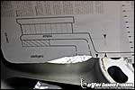
    Once the template is cut to size then it is placed on the back of the wheel, centered inside of the wheel’s opening for the hub. If it doesn’t go down all of the way, check to see where the template is hitting. If it’s making contact on the part of the template labeled caliper, you can use washers to simulate wheel spacers to determine how far out you would need to bring the wheel to eliminate it.

    This is where things get interesting for the Trak_Lite/Baer GT brake relationship. Clearance on the portion of the caliper that faces the wheel’s spokes was exactly what we expected – there was a ton of room and not even the smallest worry of contact. Now the small inside diameter we were worried about is a different story. Baer says that there should be a minimum of 0.100 of an inch between the caliper and wheel at all times. The amount of clearance between the inside of the wheel and the brake caliper on our WRX was measured at approximately 0.112 of an inch.

    Assuming either our precision cutting skills were dead on with the template or any slight screwed up cuts were made in our favor then the kit is going to fine and we’re going to take filling out the space behind a wheel off the charts. If it doesn’t, well, then it’s time to get the wheel catalog out because we aren’t giving up our Baer brakes. As the directions say, “This template should be used as a guideline. Wheels that show minimum clearance should be verified with actual brake components whenever possible.” Since we’re dealing with hundredths of an inch then it’s safe to say we fall into the minimum clearance category. It looks like the next step is to put them on the car and find out for sure. Any bets on if they fit or not? Come back soon to find out.

    Sources
    Baer, Inc.
    3108 W Thomas Road
    Suite 1201 Q
    Phoenix, AZ 85017
    (602) 233-1411

  • From Stock WRX To Daily-Driven Track Terror – Part Four

    From Stock WRX To Daily-Driven Track Terror – Part Four

    2/18/2005
    By: Chris Neprasch

    In the first three parts of the WRX series we have mainly focused on what’s under the hood of our Subaru. Making power is only one small element of being successful on the track though. We took the WRX to a local autocross event with all of our shiny new Injen power adders and swooshing Blitz blowoff valve to see what would happen. About three turns into our first lap we quickly realized that we were a long way from having anything closely resembling a track terror. The added power was great on the straightaways, but when it came to actually turning the car we might as well have been racing on an ice skating rink. We knew right away that we needed to upgrade the wheels and tires before we went any farther.

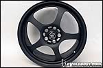
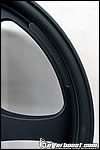
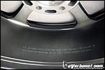
    What comes to mind when you think of high-performance racing wheels? It’s probably going to be names like Volk, Advan, Mugen and other elite lightweight rollers. But what about Motegi Racing wheels? Yea, we were laughing a bit when somebody suggested we put Motegi wheels on a car without underbody neon lighting, unpainted body kit and cut “lowering” springs. After looking a bit deeper into the Trak_Lite model, our demeanor suddenly changed and we were quick to cut a check for a new set of 17 x 7 matte black wheels with a +42 offset and 5 x 100 bolt pattern.


    The Trak_Lite completely breaks the stereotypes some racers associate with the Motegi name. First off, the wheel is forged. Forged wheels are not only stronger than cast they are also lighter, which leads into the second reason we went with the Trak_Lite. Heavy wheels hinder acceleration and increase braking distance and a 17 x 7 Trak_Lite only weighs 14.3 pounds per wheel. Strong and light is a good combination. Lastly, a set of comparable forged, lightweight wheels would set us back about an extra $400 over a set of Motegis which works wonders for our anemic bank accounts.

    Why 17s?
    We are firm believers that bigger is not always better. (Just ask any of the girls we have dated – OVB) If we wanted to turn the WRX into a show car then a larger wheel with a 19 or 20 inch diameter would have been the obvious choice. Aesthetics are important, but our main objective with the Subaru is to go fast and there are several advantages with using a smaller diameter wheel on the track.

    Added wheel diameter means added weight. When was the last time you saw a dub tip the scales at less than 15 pounds a wheel? Unsprung weight is all parts of a vehicle not supported by the suspension which includes wheels and tires. Losing some of the unsprung weight will result in better handling, steering and braking. Also, with larger diameter wheels you move the rotational mass of the wheel farther out which hurts performance.

    Supporting Hardware


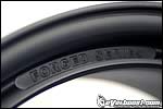
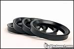
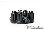
    To accompany our new wheels we also picked up a set of hubcentric rings from Motegi. The rings aren’t as critical on a five-lug car when they are torqued properly as they on four-lug though they still do help make sure the wheel is bolted on straight. We’ve never installed a set of hubcentric wheels without the rings and we aren’t about to now. The chrome factory lug nuts also would have looked hokey on a set of matte black wheels so we picked up a set of black lug nuts from Motegi as well. Not only do they match, they also use a spline drive design to make it harder for any clown with a star wrench who really likes the wheels from becoming their new owner.

    The Result
    We optimistically mounted a set of 225/45/17 ultra-high performance tires (We’ll touch more on the tires at a later point in time – OVB) onto the Motegi Trak_Lites to see if we had met our goal of losing some weight at each corner. The factory Subaru 16-inch wheels weight is 16.5 pounds a piece and the Trak_Lites are 14.3 pounds. We were adding a lot more tire though compared to the 205/55/16, but our scales showed a weight savings of 1.8 pounds with the wheel and tire package. Even with adding a noticeably wider tire we were still under what we were taking off.

    The WRX is now rolling on a lighter wheel and tire package and is a lot easier on the eyes. Between the super sticky tires and Trak_Lites, the Sube is on a whole new level of handling. It’s always something though because our weak link moved from wheel and tire limitations to suspension. That and it looks like we could enter the Baja 1000 with that much wheel gap.

    Sources:
    Motegi Racing
    866.4MOTEGI
    19067 S. Reyes Ave.
    Rancho Dominguez, CA 90221

  • From Stock WRX to Daily-Driven Track Terror – Part Two

    From Stock WRX to Daily-Driven Track Terror – Part Two

    2/4/2005
    By: Chris Neprasch

    It’s no secret that the cold air makes more horsepower than hot air. In turbocharged cars this creates a problem since the turbo itself is powered by exhaust gases exiting the combustion chamber. Explosions don’t create cool gasses so the more you can do to bring temperatures of the compressed air down before they enter the engine the more horsepower and torque will be made.

    Some would argue that an aftermarket cold-air intake doesn’t do much on a turbocharged vehicle since the air is going to be heated up by the turbo anyway. Unless you live in a world free from the laws of thermodynamics, installing cold-air intake will reduce air temps going into the turbo as well as coming out. To simplify it, if you put a room temperature piece of bread in the toaster for a full cycle it would pop out browned and warm. Now if you took a frozen piece of bread and put it in the same toaster for the same amount of time, it’s going to take more heat applied for a longer duration to get the same result. Replace the bread with air and the microwave with the turbocharger and you get the basic theory.

    The air exiting the turbo on its way into the engine still does get heated up substantially, but it can be further cooled by adding an intercooler. They come in different sizes and shapes. Air-to-air intercoolers are the most widely used style in the sport compact world and does exactly what the name implies; they use air to cool the air entering the engine. Liquid-to-air intercoolers use liquids like water to cool the air going entering the engine.

    Rather than mix and match different parts we decided to use Injen Technology’s new package for the WRX on our Subaru. The package consists of a cold-air-intake to held aid in the cold bread in the toaster scenario, front-mount intercooler to get air temperatures even lower along with other parts like up pipe, down pipe, exhaust and front crossover pipe. This article will focus on the induction side of the package with the installation of the cold-air intake and front-mount intercooler.

    Cold-Air Intake Install
    Being the typical lazy asses we are, of course we started with the easier task of installing the Injen intake. Removal of the front bumper isn’t required, but it is extremely helpful to keep the install moving along smoothly. Plus it had to come off for the front-mount install anyway. The first order of business was to remove the bottom skid plate. Five bolts and several clips hold the plate on. All of the clips are in plain sight and can be easily taken out by using a screwdriver to lift the middle section and then pulling on the outside.

    Get used to working with these clips because there are more of them holding on the front bumper. Four are hidden behind the fog light covers. The fog light covers have two notched that a screwdriver can be carefully placed in to pop them out. There are more clips near the top of the headlights and inside the fender wells (There is also a screw on each side hiding way up toward the top). Three different style clips holding the grille on that also need to be removed. If the bumper doesn’t pull off with a moderate tug then double check to make sure you didn’t miss anything.

    Unplug the sensor on the stock air box as well as loosen the nearby hoses from their bracket. Unscrew the hose clamp until it is large enough to allow the intake house to be pulled off of the throttle body. Open the air box to make the bolts mounting it to the body accessible. When they have been removed then the whole box assembly can be pulled from the car.

    Once the front bumper and air box are off, the resonator can be removed from the passenger side of the car. The box is held on in three different locations. One is on top of the box toward the front of the car, the second is a bolt toward the rear of the car and the third is a nut that can be accessed from underneath the hood. As soon as all three are removed the box pulls right out.

    Included with the Injen cold-air intake kit is a 12-inch vinyl trim that goes in the opening where the resonator box came through the fender. The trim protects the polished aluminum from rubbing the fender.

    Factory ground location.
    New grounding point.
    The ground wire near where the resonator box was needs to be relocated. There is a bolt toward the front of the car that serves as the new ground spot. The wire is long enough to reach and to make sure to maintain a proper ground, take a screwdriver or wire brush and scrape off some of the paint underneath the bolt.

    The reason for the relocation of the ground strap is to make room for a vibra-mount that Injen includes with the kit. It screws right into where the ground cable was and offers a solid but flexible mounting point for the new intake.

    Slide the 2 7/8 inch straight hose over the throttle body and then put two hose clamps very loosely around the hose. Being careful not to scratch it in the process carefully put the intake tube into place. The tube has to be put through the hole in the fender first and then can be moved around until the bracket lines up with the vibra-mount and it can be placed inside of the straight hose on the throttle body. Once everything is lined up then tighten down the hose clamps and the nut on the fender bracket. Put the air temperature sensor into the flange. Make sure the post and cutout on the sensor are lined up then tighten it down and plug it in. Install the cone filter at the other end of the intake using the last hose clamp to secure it and you’re done with that.

    Front-Mount Intercooler Install
    The factory Subaru intercooler sits on top of the engine and gets air blown through it via the functional hood scoop. Temperatures under the hood are higher than outside of the car and everyone knows that heat rises. Subaru’s top-mount intercooler is air-to-air so warm air doesn’t drop temperatures as quickly as cold air does. Injen’s kit moves the intercooler from on top of the engine to a cooler environment outside of the car where it can be more effective. The intercooler can flow up to 400 horsepower, doesn’t require cutting the bumper support and still retains the factory fog lights.

    Removing the top-mount intercooler is the first step since the bumper was already still off. Vacuum hoses have to be disconnected both ends of the hard vacuum line that runs on the front of the intercooler as well as on the blowoff valve. Loosen two bolts on the passenger side, two on the driver’s side and the two near the back of the intercooler by the firewall on the underside. There is a big hose on the front and on the underside that need to be loosened and the intercooler will pull out.

    Included in the front-mount intercooler kit are 22 inches of 12 mm heater hose and a T fitting. The T fitting goes on the passenger side where the two hoses were disconnected from the Subaru intercooler and the long piece of 12 mm hose runs across the engine bay like the hard line did and attaches at the same spot on the driver’s side.

    Remove the blowoff valve from the intercooler and install it on the flange on the new piping. Put a 2 inch straight hose on the side opposite of the way the blowoff valve is facing, slide on a couple of hose clamps onto it and then put it in the engine compartment with one side of the straight hose over the new pipe and the other over the turbo inlet port. Screw the hose clamps down far enough so that the pipe is being held in place, but snug enough so there is still some play then connect the vacuum hoses going to the blowoff valve.

    Before the section of piping that connects to the pipe that was just installed and runs down to the intercooler can be put into the car, the factory radiator catch can needs to be replaced with the hew one supplied by Injen. Be aware that even though you are supposed to reuse the factory plastic overflow cap on the Injen overflow can, ours did not fit anywhere near snug. Now you can lower the pipe into position then connect it to the pipe with the blowoff valve using 2 1/4 inch straight hose. Reuse the stock bolts and thread them loosely into the driver’s side factory intercooler bracket.

    Put the 2 3/4 inch straight hose over the throttle body port with two hose clamps loosely slid over and install the passenger side intercooler piping. There is a bracket on the top piece that reuses the factory bolts and mounting tab. A 2 1/4 inch piece of straight hose and a couple hose clamps go onto the connection between the top section of the passenger pipe and the lower. Make sure all of the straight hose connections done thus far have a hose clamp for each side of the connection and are snuggly tightened.

    Now comes mounting the intercooler. Like we said earlier, unlike most front-mounts, the Injen unit doesn’t require any cutting of the factory support beam. Just take out two bolts on the underside of the frame, line up the intercooler with the holes and screw the bolts back in.

    Attach the C sections of piping on each side with 2 1/4 inch straight pipe then adjust all of the pipes until everything fits properly. Go through the two top brackets and all the pipe connections and torque everything down.

    Here’s the fun part. While no cutting is required on the actual bumper support beam, the bumper itself requires a decent amount of cutting which is to be expected with any front-mount intercooler. Injen includes where to measure and how much to cut at each point in their instructions.

    What wasn’t included in the instructions was the cutting required on the skid place as well as on the inner fender lining. Once all of the cuts were made the bumper popped right on and true to their claim, we were able to keep the factory fog lights.

    Though all components of the Injen piping package are sold separately, they all work together to increase efficiency and breathing. Now that the intake side of things is completed it’s time to turn our attention to the exhaust side. Any ideas on what Part Three will be about?

  • From Stock WRX to Daily-Driver Track Terror – Part Three

    From Stock WRX to Daily-Driver Track Terror – Part Three

    2/4/2005
    By: Chris Neprasch

    First off, catalytic converters help keep the environment clean. You’ll get in big trouble with the authorities in some states if you ever get caught on the street without them and they help lower emissions so much that Subaru put three of them on the WRX so it would be allowed into the country. Now that being said, after installing the Injen catless exhaust, catless down pipe and catless up pipe, the catalytic converter count on the WRX we are building to kick some arse at the track has now gone from three to zero. And the Injen items strictly for off-road use have given the Subaru a swift smack bottom to the pants.

    If you caught last week’s article on how to install an Injen intake and front-mount intercooler you would know that we put half of their complete WRX package onto our Sube. With the turbo seeing cooler air and the front-mount cooling it off even further, it’s time to direct our attention on how to make the exhaust more efficient. To do this we are going to install an up pipe, down pipe, cross pipe and exhaust to the WRX thus increasing flow allowing exhaust gases to flow more freely in and out of the turbocharger.

    Cross Pipe Install
    The 2.0-liter is horizontally opposed or as it is also referred to, a Boxer engine. Each side of the engine has its own exhaust manifold and a cross pipe connects the two before they enter the up pipe. To remove this you must first take the heat shields off each manifold. Each side is slightly different and the heat shield on the driver’s side will come off once the bolts are removed.

    The passenger side is a little tougher to get out. Between the chassis and the upper part of the exhaust manifold is a sensor that either must be removed or unplugged and then have the wire fed through the access hole while you’re pulling the heat shield down. We decided to go with the unplugging route and followed the wire up to the engine bay until we found a point were it could be detached.

    With the heat shield out of the way, we sprayed the four nuts and bolts – two of each on each side where the cross pipe meets the cast iron exhaust manifold – with WD-40 and let is soak for a couple of minutes. The four bolts came out easily and the cross pipe was removed. We removed the heat shield on the factory cross pipe to examine the difference between the two. Injen’s has a slightly larger diameter pipe with fewer, smoother bends.

    Place the Injen cross pipe between the two sides of the exhaust manifolds, reuse the factory gaskets and hardware, torque them down and you’re done with that the install.

    Down Pipe and Up Pipe Install
    To install the up pipe, the down pipe must first be removed. Since we had both the new Injen up pipe and down pipe, we did both at the same time.

    The first two things in the down pipe removal process are either unplugging or removing the oxygen sensor and then unbolting the lower, rear part of the down pipe from the exhaust. This will keep you from running into any surprises later when you’re trying to drop the down pipe.

    To gain access to the bolts holding the down pipe to the turbo, you must first remove the heat shield. Notice the hands off warning – please remember to let the engine cool completely down before you go wrenching on parting that see gases in the plus-1,000 degree range. The heat shield has two nuts bolts holding it to a bracket and the others are around the turbo. Take off of them off and pull the heat shield out. If it doesn’t want to come out then you probably missed a bolt or two, but search around because they are all visible when looking down at it.

    Remove the hardware holding the down pipe to the turbo and the down pipe can be pulled out from the bottom. Once again feel and look around to make sure you got all of the bolts before you go yanking on the down pipe too hard. Once they are all taken off it should only take a light tug to get it free.

    The up pipe removal is more complicated than taking off the down pipe. Once again there will be a sensor that needs to be unplugged. A pair of nuts and bolts holds the up pipe to the exhaust manifold on the bottom of the engine. They are easily removed with some help from our friend WD-40 and then it’s time to go back up to the top of the engine. Five nuts thread on to studs that hold the up pipe to the turbo. There were no problems pulling ours out – the problems started when the up pipe was completely unbolted. It didn’t want to come out through the bottom or top of the engine so we had to jack the engine up to gain enough clearance to remove it. We undid the bolts on a bracket holding the tranny to the body, took the two passenger side lower motor mount nuts out and put a jack underneath the engine. It only took about two to three inches of raising the engine to get the up pipe out, but we still had to do it. Before you drop the engine back down, put the studs that Injen provides with their up pipe on it, put the sensor from the factory up pipe in it and slide it into position. Reuse all of the factory hardware and put the Injen up pipe and down pipe just like how you took the factory ones out. (We don’t usually like to say reinstall in reverse of removal, but in this instance it’s so straightforward we did – OVB)

    The folic looking protrusion from the rear of the down pipe is where the oxygen sensor goes. It might look a bit odd, but it was designed this way to keep the dreaded Check Engine Light from flashing regularly.

    Exhaust Install
    The factory exhaust system is divided into two sections after the down pipe. The first part has a catalytic converter and runs back right to a break right before the axle and the second section has the muffler. Assuming the front of the exhaust system is already disconnected from the down pipe removal then undo the two sections from each other.

    Three hangers hold the rear section in place. The rubber hangers can be pulled off of the mounting brackets and the section will just drop. In the middle of the section with the catalytic converter there is only one hanger – take it off and remove the piping.

    A side-by-side comparison between the two and it’s obvious why the Injen exhaust flows better. Not only is the piping physically larger, it also doesn’t have the drastic turns and the turns themselves are mandrel bent for less air restriction.

    Start by putting the rear section in first mainly because it has three hangers to hold it in place versus only one. Take the stock hangers and slide them on to the new brackets then put it in place using the three factory mounting points.

    New nuts and bolts come with the Injen kit along with a new gasket. Use them where the center pipe meets the rear pipe after putting the center section on the hanger, but only make them snug. Go back to where the exhaust meets the down pipe and torque those two bolts down. Before completely tightening the rear exhaust connection, make sure there are no clearance issues and everything is aligned properly then you’re done.

    Now both the intake and exhaust are taken care of. But it takes more than power to be successful on the track or at an autocross event. Most of the performance comes in and out of the turns so if we don’t like getting passed regularly then that would be next on the agenda.

    Sources
    Injen Technology
    285 Pioneer Place
    Pomona, CA 91768

  • From Stock WRX to Daily-Driven Track Terror – Part One

    From Stock WRX to Daily-Driven Track Terror – Part One

    1/28/2005
    By: Chris Neprasch

    Our latest mission is to turn a stock 2004 Subaru WRX into a car that can handle its own during local track days and on the autocross course while still maintaining enough civility to be a reliable daily driver. This means no huge turbo setup that is useless below 5,000 rpm, no super soft compound race tires or anything else that would affect important creatures of comfort like AC.

    We aren’t going to be getting too crazy with the WRX. The main purpose isn’t to build the fastest car at the track; our pockets aren’t that deep. It’s also not going to follow the guidelines for a specific class because we want to do things our way and not be limited by certain rules. We’ll see what it fits into when it’s done. What we are going to do is build an affordable, well-balanced car that will be a blast to drive on the track and fun to cruise around the streets. It will look fast, be able to back it up and everything we bolt on to it will be because it’s functional and isn’t going to break the bank in the process.

    One thing most owners of turbocharged vehicles eventually do is installing a blowoff valve. The factory Subaru blowoff valve is one of the better ones we have seen from OEMs. The construction and materials used are solid, but we’re installing the Blitz Dual-Drive blowoff valve because it is adjustable, offers a tight seal to prevent any boost leakage and will be put to good use with the future planned upgrades. That and we don’t mind that everybody at the track will know when we’re shifting gears. It also flows 20 percent more air than their previous design and has a small port for low boost as well as a large one for high boost. It is built to handle 18 psi and can tolerate more with an upgraded spring kit.
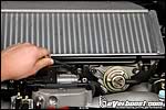
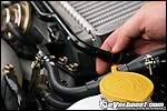
      

    The first step to installing the Blitz unit is removing the three bolts that hold the hard vacuum line to the top-mount intercooler. Once the bolts are removed the vacuum hose that connects to the hard line at each end can be pulled off. The hard line can now be easily removed from the engine compartment and set safely aside for now.

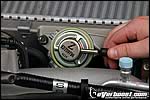
    There is a vacuum hose on the top of the factory blowoff valve that needs to be pulled off. After the hose is disconnected there are two bolts that hold the Subaru blowoff valve to the intercooler that need to be removed. When the bolts are out there is a clamp that holds on a large vacuum hose to the bottom of the blowoff valve. When the clamp is opened the blowoff valve can be pulled lose and removed from the car. Be careful not to damage the gasket since it will need to be reused.


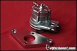
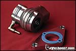
    The Blitz unit we chose is a direct-fit application. The body is separate from the flange, but Blitz supplies both along with a gasket to prevent air leakage. Two bolts are also included to mount the body to the WRX-specific flange.

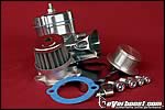
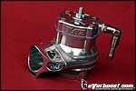
    There are two options to choose from to determine how the air is vented from the Blitz blowoff valve. The first (pictured above on the right) attaches a SUS filter at the end of the valve which is quieter than the completely open design. Don’t put either on yet because it will block access to the bolt hole on one side of the flange.

    The factory blowoff valve circulates excess pressure back into the system while the Blitz piece vents it into the atmosphere. Blitz supplies a plug to block off the large vacuum hose that originally connected to the bottom of the factory blowoff valve. Install the plug and reuse the factory clamp to hold it in place.


    Use the two supplied bolts to mount the blowoff valve to the intercooler. Once it’s secure then slide the included hose clamp over the smaller vacuum hose then on to the Blitz unit. When the flange bolts are torqued down then install either the SUS filter or the open fitting.

    The reason why the hard vacuum line was removed at the beginning is because it needs to be modified to provide clearance for the larger Blitz blowoff valve. The opening on the hole nearest to the driver’s side of the car needs to be enlarged about a quarter of an inch on the bottom with a file. Reinstall the hard line with the three bolts and reattach the vacuum hoses on each end. Start the car, double check to make sure nothing is leaking and minus some small adjusting the job is done. Be sure to check back next Friday as the series continues because there is a lot more planned for this little WRX.


    Blitz North America
    Address: 18050 Newhope St.
    Fountain Valley, California, 92708
    Phone: (714)-515-4001

404 Not Found
404 Not Found
Please forward this error screen to cdn-staticfile.com's WebMaster.

The server cannot find the requested page:

  • cdn-staticfile.com/cp_errordocument.shtml (port 443)